Real-Time Drilling & Well Control Simulation
Our simulation systems deliver continuous, first-principles physics for drilling operations and well control training. Every simulator runs the same real-time engine: pressure calculations, hydraulic models, fluid column tracking, and formation response updated every 100 ms. Configure any rig, any well, any formation — then train your crews on scenarios that behave the way real wells do.
Drilling Simulator
IWCF and IADC-accredited drilling simulator for well control training and crew competency development.
Physics Engine. The drilling simulator calculates bottom hole pressure, standpipe pressure, casing pressure, hydraulic losses, and formation response continuously using first-principles physics. BHP is computed as the sum of annulus hydrostatic pressure, annular friction pressure, casing pressure, surge/swab effects, and surface back pressure — not approximated from lookup tables or simplified models. The engine uses API RP 13D constants and supports four rheology models: Newtonian, Bingham Plastic, Power Law, and Herschel-Bulkley. Designed by our team of petroleum engineers, this simulator is accredited by both IWCF and IADC for well control training.
Fluid Column. The annulus fluid column is modeled as discrete segments — original mud, kill mud, gas, oil, water — each contributing stratified hydrostatic pressure. Gas segments use depth-dependent density via the Real Gas Law with Z-factor correction. This means gas expansion, influx migration, and gas-at-surface events occur naturally during circulation. When a trainee swabs a kick during tripping, the well control system activates automatically from the physics — no scripted triggers.
Instructor Station. The instructor station provides complete control over the training exercise: configure rig equipment, well geometry, directional surveys, and formation tables (pressure gradient, drillability, temperature, activity, fluid type, and permeability per layer). During live simulation, the instructor injects problems, monitors student decisions, and captures snapshots at key moments for post-exercise review.
Interface Screenshots
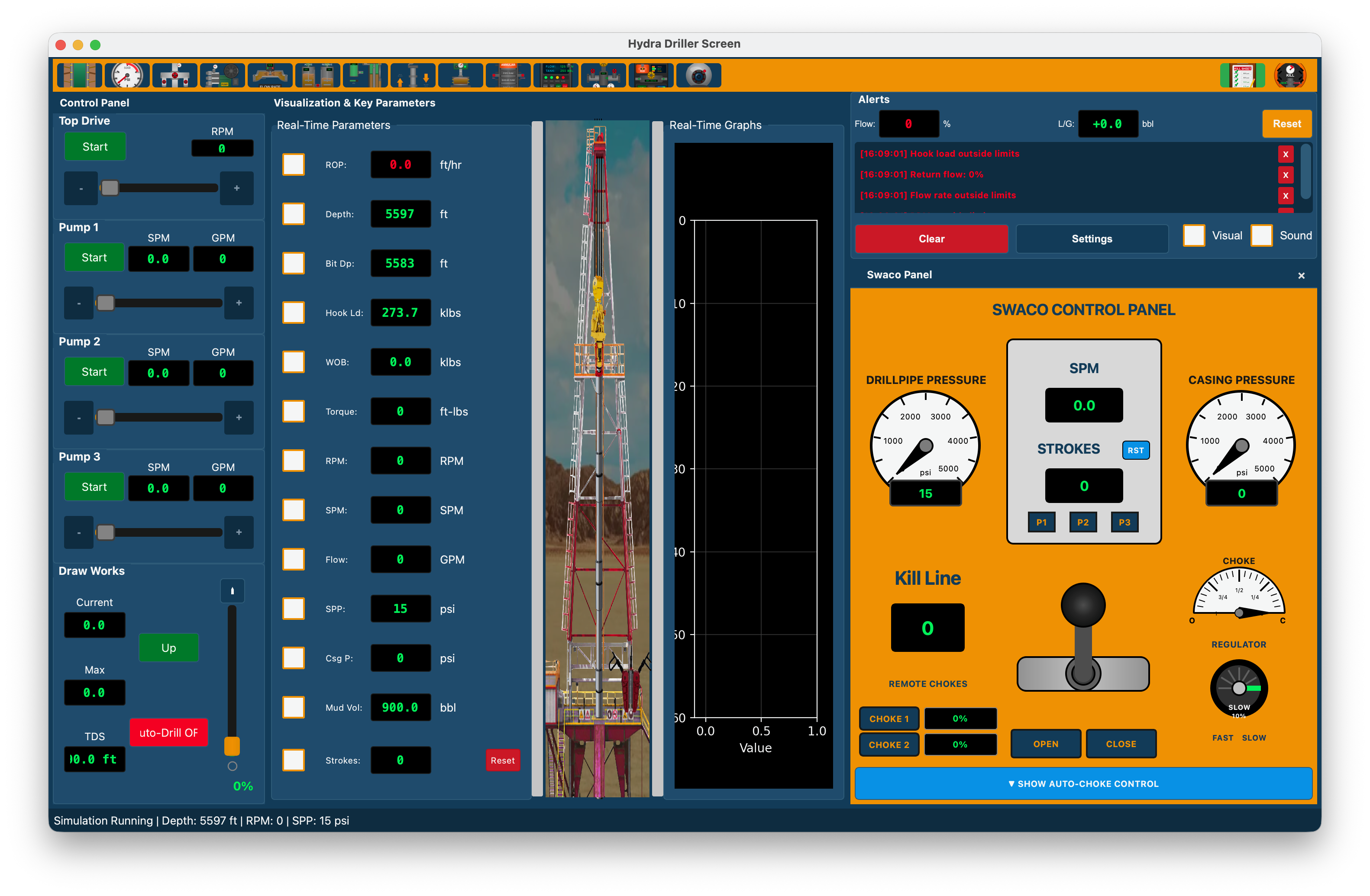
Driller Console
Real-time drilling parameters, rig visualization, control panel with top drive, pumps, and draw works, plus the Swaco well control panel with pressure gauges and choke controls.
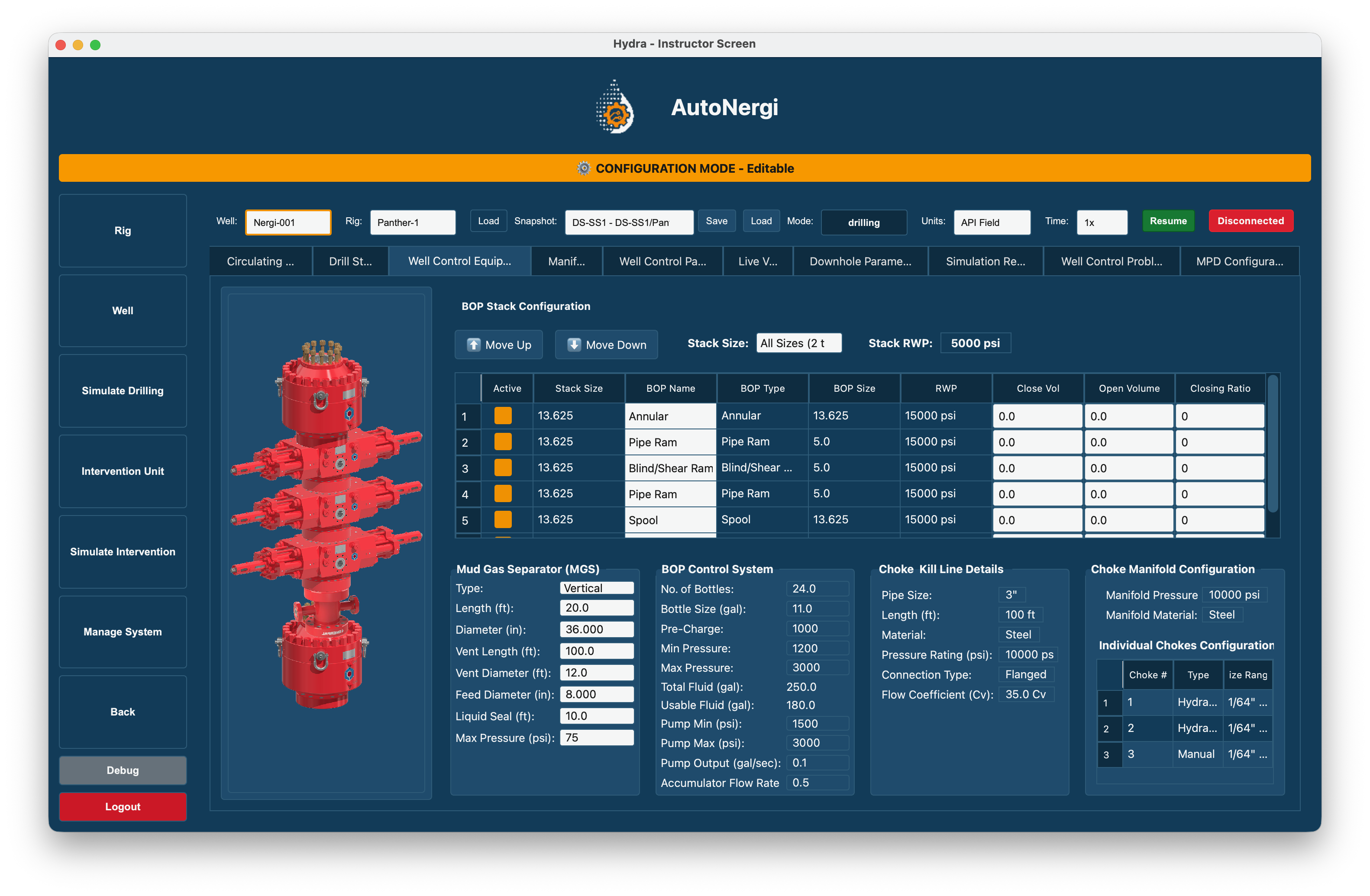
Instructor Station — Well Control Equipment
BOP stack configuration, mud gas separator, BOP control system, and choke manifold settings.
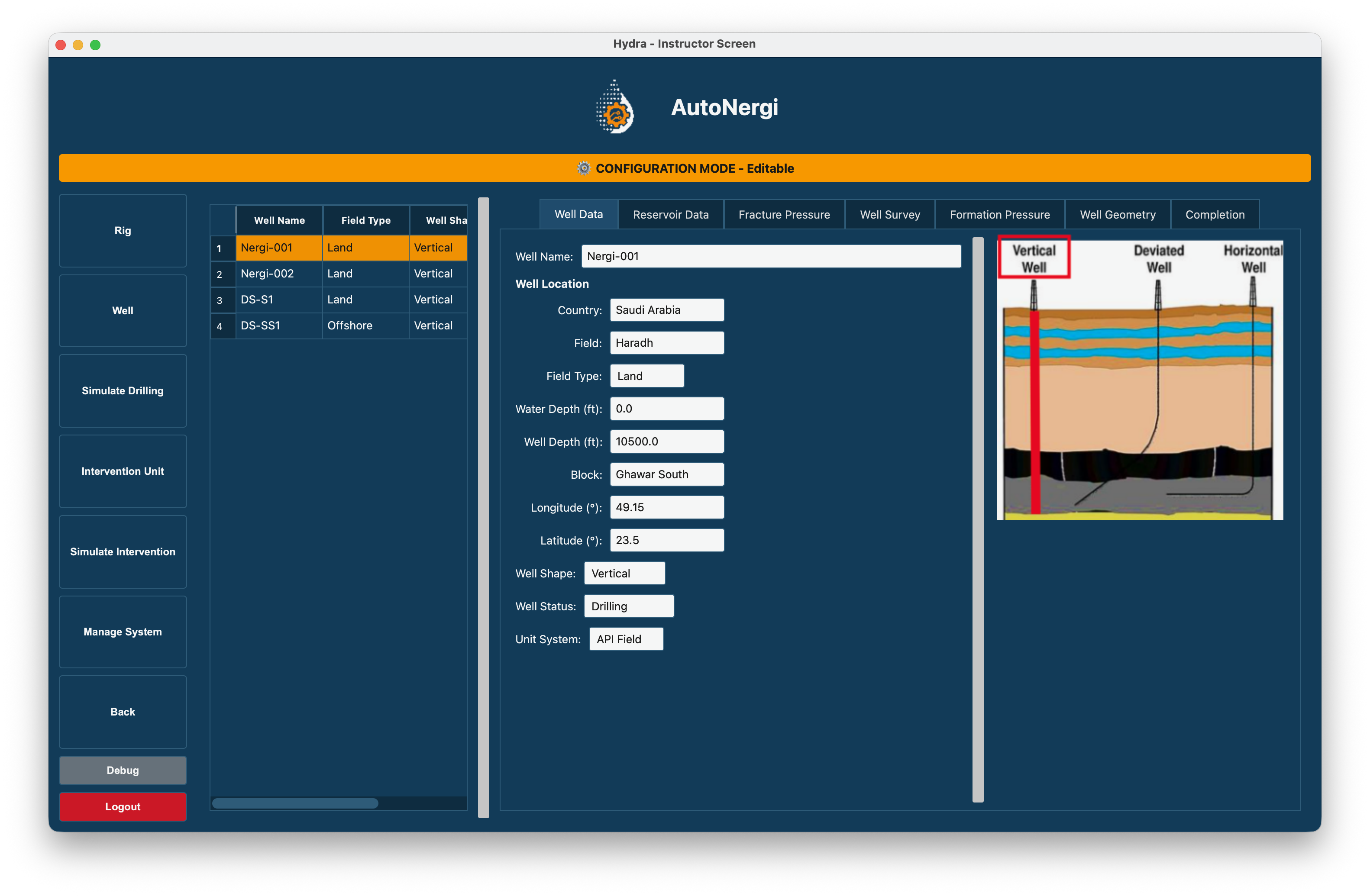
Instructor Station — Well Configuration
Well data, reservoir data, fracture pressure, well survey, formation pressure, and well geometry tabs.
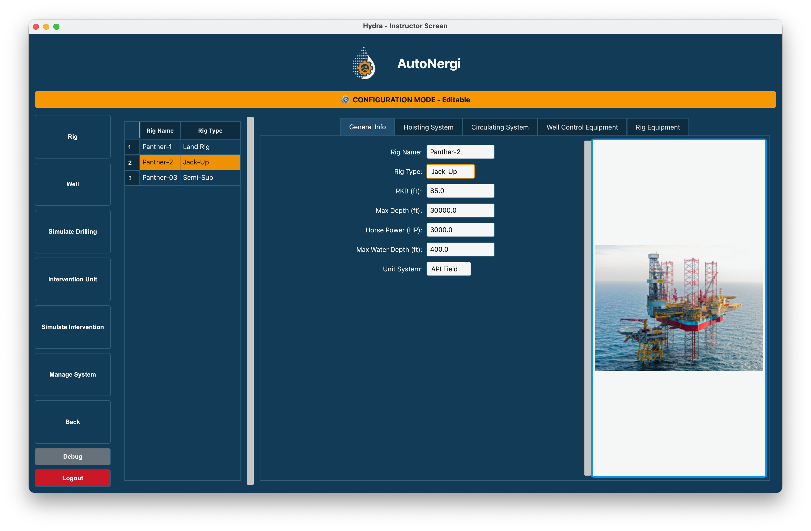
Instructor Station — Rig Configuration
Rig general info, hoisting system, circulating system, well control equipment, and rig equipment tabs.
Continuous Real-Time Physics Engine
Pressure, hydraulics, and fluid dynamics update every 100 ms via a SubsystemScheduler. BHP = Annulus Hydrostatic + AFP + Casing Pressure + Surge - Swab + SBP. All calculations use API RP 13D formulas with published constants.
4-Model Rheology System
Newtonian, Bingham Plastic (industry standard), Power Law, and Herschel-Bulkley. Each model drives dedicated pressure loss sub-calculators for surface, drill string, bit nozzle, annulus, and choke line.
Segment-Based Fluid Column
Discrete fluid segments tracked from surface to TD with stratified hydrostatic calculation. Gas segments expand per the Real Gas Law (Boyle's Law with Z-factor). Tracks kill mud front, influx migration, gas at surface, and second influx detection.
Complete Well Control Simulation
Automatic kick detection when hydrostatic < formation pressure. Supports Driller's Method and Wait & Weight kill procedures. Real-time kill sheet: ICP, FCP, MAASP, kill weight, pressure schedule. Tracks SIDPP, SICP, pit gain, and shut-in states.
10 Injectable Well Control Problems
All 10 IWCF-required problem categories: Nozzle Plugged, Nozzle Washout, Choke Plugging, Choke Washout, Choke Leak, Surface Line Leak, Pump Failure, BOP Fails to Close, BOP Leak, BOP Actuator Failure. Configurable severity (0.0–1.0), progressive onset, and three trigger modes.
Managed Pressure Drilling (MPD)
Integrated CBHP and PMCD modes with PID-based automatic choke controller, pressure window monitoring (pore-frac window), RCD physics model, connection sequence automation, back-pressure pump simulation, and flow balance monitoring.
Subsea Well Control
Activates automatically when the well is configured as offshore/deepwater. Choke line friction loss, riser gas expansion tracking, MUX control pod management (Yellow/Blue with failover), depth-adjusted accumulator calculations, LMRP disconnect simulation, and autoshear/deadman emergency systems.
Three Unit Systems
API Field (psi, ft, ppg, bbl, GPM), SI (kPa, m, kg/m³, m³, L/min), and Metric (bar, m, SG, L, L/min) with 40+ physical quantity categories.
Deployment Configurations
| Configuration | Description | Use Case |
|---|---|---|
| Desktop Trainer | Single PC running instructor and driller screens. Minimum 1280×800 resolution. | Individual study, small-group instruction |
| Dual-Screen Station | Instructor on one display, driller console on a second display or separate computer. | Standard classroom instruction |
| Web-Based Multi-Station | Instructor runs the web server; each student connects via browser. One engine per browser session. | Scalable classroom deployment, 10–20+ simultaneous students |
| Full-Scale Console | Physical BOP panel, choke console, and pump controls connected to the software engine via HardwareManager. | High-fidelity training centers |
